Top 10 Solar Project Solution Factory In China
Photovoltaic off-grid power generation system is mainly used to solve the problem of basic electricity consumption for residents in areas without electricity or electricity. The photovoltaic off-grid power generation system mainly consists of photovoltaic modules, brackets, controllers, inverters, batteries and power distribution systems. Compared with the photovoltaic grid-connected system, the off-grid system has more controllers and batteries, and the inverter directly drives the load, so the electrical system is more complicated. Since the off-grid system may be the only source of power for the user and the user has a large dependence on the system, the off-grid system design and operation are more reliable.
Common design problems with off-grid systems
Photovoltaic off-grid systems do not have uniform specifications, and should be designed according to user needs, mainly considering the selection and calculation of components, inverters, controllers, batteries, cables, switches and other equipment. Before the design, the pre-work should be done well. You need to understand the user's load type and power, the climatic conditions of the installation site, the user's electricity consumption, and the requirements to be clear before you can do a good job.
The voltage of the component and the voltage of the battery should be matched. The PWM type controller solar module and the battery are connected by an electronic switch, and there is no device such as inductance in the middle. The voltage of the component is between 1.2-2.0 times of the voltage of the battery. It is a 24V battery, the input voltage of the component is between 30-50V, the MPPT controller has a power switch tube and an inductor circuit in the middle. The voltage of the component is between 1.2-3.5 times of the voltage of the battery. If it is a 24V battery, The component input voltage is between 30-90V.
Frequently asked questions when debugging off-grid systems
1
Inverter LCD is not displayed
01
Failure analysis
Without the battery DC input, the inverter LCD power supply is powered by the battery.
02
Possible Causes
(1) The battery voltage is not enough. When the battery is just shipped from the factory, it is usually fully charged, but if the battery is not used for a long time, it will be slowly discharged (self-discharge). Off-grid system voltages are 12V, 24V, 48V, 96V, etc. Some applications require multiple batteries in series to meet the system voltage. If the connection cable is not done well, the battery voltage will be insufficient.
(2) The battery terminals are reversed. The battery terminals have positive and negative poles, generally red for the positive pole and black for the negative pole.
(3) The DC switch is not closed or the switch is faulty.
03
Solution
(1) If the battery voltage is not enough, the system can't work, the solar energy can't charge the battery, go to another place to charge the battery to more than 30%.
(2) If it is a problem with the line, measure the voltage of each battery with a multimeter voltage file. When the voltage is normal, the total voltage is the sum of the battery voltages. If there is no voltage, check whether the DC switch, terminal block, cable connector, etc. are normal.
(3) If the battery voltage is normal, the wiring is normal, the switch is also turned on, and the inverter is still not displayed, it may be that the inverter has failed, and the manufacturer should be notified for maintenance.
2
Battery can't be charged
01
Failure analysis
The battery is charged by the PV module and controller, or by the mains and controller.
02
Possible Causes
(1) Component reasons: The component voltage is not enough, the sunlight is low, and the components and DC cable are not well wired.
(2) The battery circuit wiring is not good.
(3) The battery is fully charged and reaches the highest voltage.
03
Solution
(1) Check whether the DC switch, terminal block, cable connector, component, battery, etc. are normal. If there are multiple components, separate the tests separately.
(2) When the battery reaches full charge, it can't be recharged, but the voltage is different when different batteries are fully charged. For example, the battery with rated voltage is 12V. When the battery is fully charged, the voltage is between 12.8~13.5V. The specific gravity of the electrolyte when the battery is fully charged. The maximum pressure limit should be adjusted according to the model of the battery.
(3) Input overcurrent: The charging current of the battery is generally 0.1C-0.2C, and the maximum does not exceed 0.3C. For example, a lead-acid battery 12V200AH, the charging current is generally between 20A and 40A, and the maximum cannot exceed 60A. The component power is matched to the controller power.
(4) Input overvoltage: The input voltage of the component is too high, check the voltage of the panel. If it is high, the possible reason is that the number of strings in the panel is too large, and the number of strings in the panel is reduced.
3
Inverter shows overload or cannot start 01
Failure analysis
The load power is greater than the inverter or battery power.
02
Possible Causes
(1) Inverter overload: The inverter overload exceeds the time range, the load power exceeds the maximum value, and the load is adjusted.
(2) Battery overload: The discharge current is generally 0.2C-0.3C, the maximum does not exceed 0.5C, and the 1V 12V200AH lead-acid battery has a maximum output power of 2400W. Different manufacturers and different models have different specific values. .
(3) The load is a load such as an elevator that cannot be directly connected to the output of the inverter. Because the elevator is falling, the motor reverses, and a back electromotive force is generated. When entering the inverter, the inverter is damaged. If an off-grid system is necessary, it is recommended to add a frequency converter between the inverter and the elevator motor.
(4) Inductive load starting power is too large.
03
Solution
The rated power of the load is lower than the inverter power, and the peak power of the load cannot be greater than 1.5 times the rated power of the inverter.
Battery FAQ
1
Short circuit phenomenon and cause
The short circuit of the lead-acid battery refers to the connection of the positive and negative electrodes inside the lead-acid battery. The short circuit phenomenon of lead-acid batteries is mainly manifested in the following aspects:
The open circuit voltage is low and the closed circuit voltage (discharge) quickly reaches the termination voltage. When a large current is discharged, the terminal voltage drops rapidly to zero. When the circuit is open, the electrolyte density is very low, and the electrolyte may freeze in a low temperature environment. When charging, the voltage rises very slowly and remains low (sometimes reduced to zero). When charging, the temperature of the electrolyte rises very quickly. When charging, the density of the electrolyte rises very slowly or almost unchanged. Do not take bubbles or gas when charging.
The main reasons for the internal short circuit of lead-acid batteries are as follows:
The separator is of poor quality or defect, so that the active material of the plate passes through, causing the positive and negative plates to be in virtual contact or in direct contact. The separator is clamped to cause the positive and negative plates to be connected. The active material on the plate expands and falls off, and the active material is deposited too much, so that the lower edge or the side edge of the positive and negative plates and the deposits are in contact with each other to cause the positive and negative plates to be connected. The conductive object falls into the battery, causing the positive and negative plates to be connected.
2
Plate sulfation phenomenon and causes
The plate sulphation system is a white hard lead sulphate crystal formed on the electrode plate, and it is very difficult to convert to lead sulfate of the active material during charging. There are several main phenomena after the sulphation of lead-acid battery plates:
(1) The lead battery rises rapidly during the charging process, and its initial and final voltages are too high, and the final charging voltage can reach 2.90V/single cell.
(2) During the discharge process, the voltage drops rapidly, that is, it drops to the termination voltage too early, so its capacity is significantly lower than other batteries.
(3) When charging, the temperature of the electrolyte rises rapidly and easily exceeds 45 °C.
(4) At the time of charging, the electrolyte density is lower than the normal value, and bubbles are generated prematurely during charging.
There are several reasons for causing plate sulfation:
(1) The lead battery is initially charged insufficiently or the initial charge is interrupted for a long time.
(2) The lead battery is not fully charged for a long time.
(3) Failure to charge in time after discharge.
(4) Frequent over-discharge or low-current deep discharge.
(5) If the electrolyte density is too high or the temperature is too high, lead sulfate will be deeply formed and difficult to recover.
(6) Lead-acid batteries have a long shelf life and are not used for a long time without regular charging.
Solar power generation "revolutionary products" in the history of power generation (our advantage)
Higher returns: Solar power generation is a clean power source compared to some traditional thermal power sources.
Lower construction costs: until 2018, the cost of PV distributed construction is at a minimum and efficiency is higher.
Longer life: thermal power needs to generate electricity every year. Solar power generation has a service life of up to 25 years, with no maintenance costs during use and a longer service life.
The construction is even less difficult: the roof can be easily and safely installed with professional photovoltaic brackets, whether it is glazed tile or color steel tile or flat roof.
Safer to use: Widely used in factories and commercial roofs, strict quality system to ensure safety.
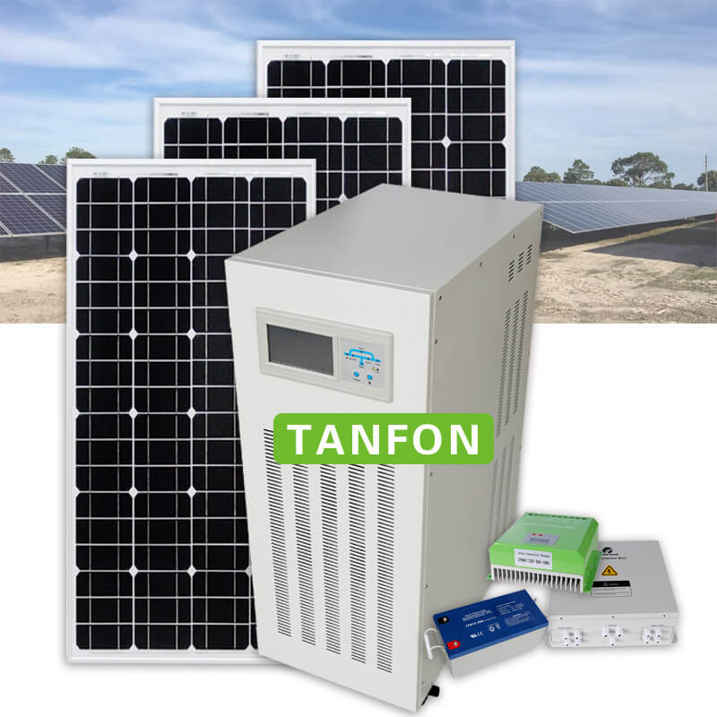
Solar single crystal / polycrystalline photovoltaic modules (our products)
The necessary components of the entire solar power supply system are introduced:
The solar power supply system is composed of a solar cell module, a solar controller, and a battery (group). If the output power is AC 220V or 110V, you need to configure the inverter. The role of each part is:
(1) Solar modules: Solar modules are the core part of solar power systems and the most valuable part of solar power systems. Its role is to convert the radiant energy of the sun into electrical energy, or send it to a battery for storage, or to drive the load. The quality and cost of solar modules will directly determine the quality and cost of the entire system.
(2) Solar controller: The function of the solar controller is to control the working state of the whole system and to protect the battery from over-charge protection and over-discharge protection. In places with large temperature differences, qualified controllers should also have temperature compensation. Other additional features such as light control switches and time control switches should be optional for the controller.
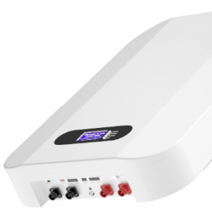
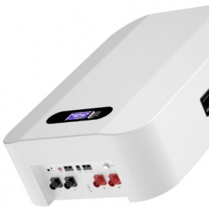
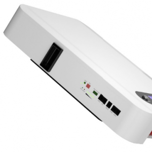
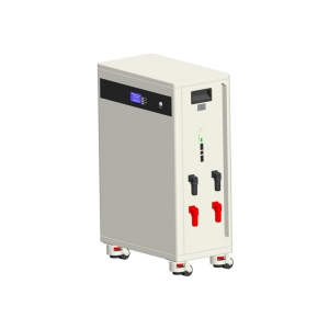
(3) Battery: Generally it is a colloidal battery. In a small and micro system, a nickel-hydrogen battery, a nickel-cadmium battery or a lithium battery can also be used. Its function is to store the electrical energy supplied by the solar cell module when there is light, and then release it when needed.
(4) Inverter: In many occasions, 220VAC and 110VAC AC power supply are required. Since the direct output of solar energy is generally 12VDC, 24VDC, 48VDC. In order to supply electrical energy to 220 VAC appliances, it is necessary to convert the DC power supplied by the solar power supply system into AC power, so a DC-AC inverter is required. In some cases, when a load of multiple voltages is required, a DC-DC inverter is also used, such as converting 24 VDC of electrical energy into 5 VDC of electrical energy (note that it is not a simple step-down).
The design of a solar powered system requires consideration of the following factors:
1. In which area is the solar power supply system used? What is the radiation situation in the area?
2. What is the load power of the system?
3. What is the output voltage of the system, DC or AC?
4. How many hours does the system need to work every day?
5. How many days does the system need to be powered continuously in the event of rainy weather without sunlight?
6, the load situation, pure resistance, capacitive or inductive, how much starting current?
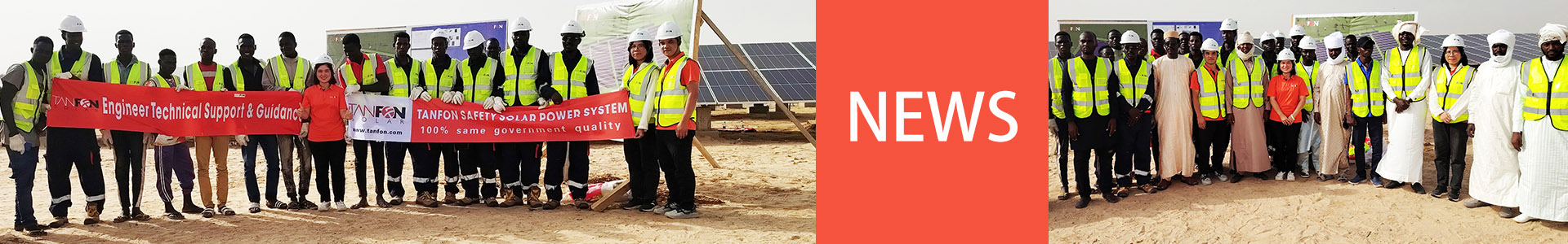
welcome send inquiry to us ,TANFON team will help you design the right system for you .


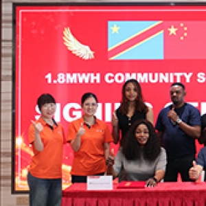
The King of the Democratic Republic of the Congo has provided a solar energy storage power station system for the village of Bunkeya to meet the electricity needs of 2500 small households in the village. As the village currently lacks access to the grid, the King requested the design of a 1MW solar panel system paired with a 1.8MWh lithium battery storage system to power the entire village.

Top 10 Solar Project Solution Factory In China


Address: 4th Floor, No. 7 Hongde Road, Nanzhuang, Chancheng District, Foshan City, GuangDong Province, China